

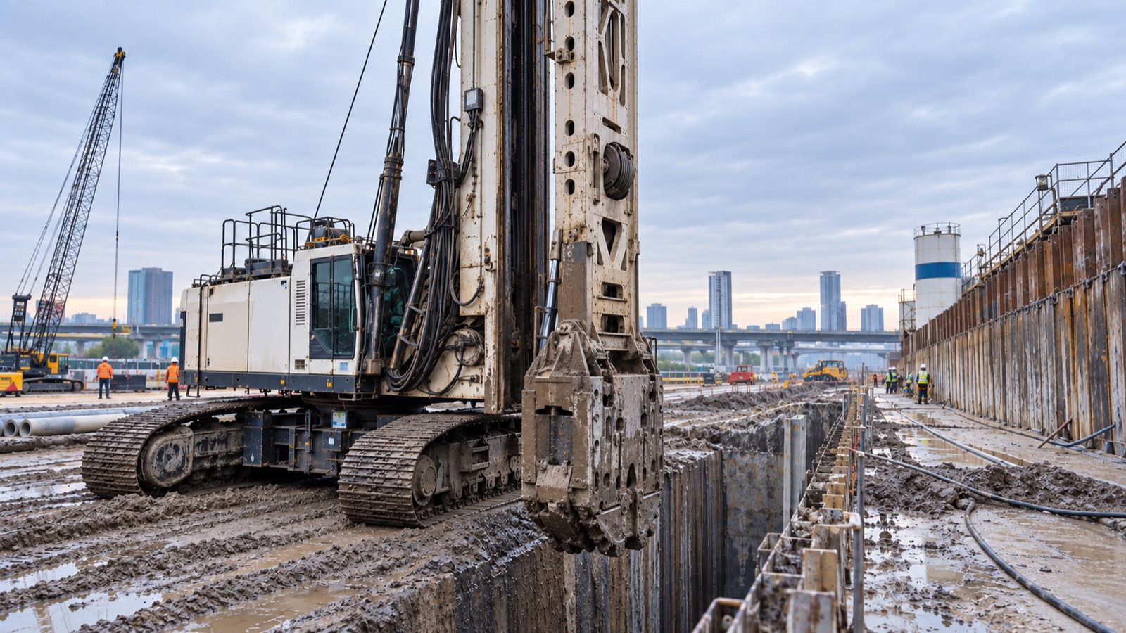
Deep Trench Cutter Verticality Monitoring with CAN Inclinometers
Vigor supplied a multi-sensor CAN inclinometer system for real-time verticality monitoring and deviation correction during 100-meter underground trench cutting.
DEEP TRENCH CUTTER VERTICALITY MONITORING
PROJECT BACKGROUND
Deep trench cutting for underground construction requires continuous verticality control. In this project, the machine was required to cut to a depth of approximately 100 meters while keeping the resulting groove within the specified vertical alignment. Small deviations near the surface can develop into substantial positional errors at depth, so operators needed reliable real-time inclination data rather than periodic manual checks.
THE MEASUREMENT CHALLENGE
The monitoring system had to operate on heavy construction equipment exposed to strong vibration, mud, water and installation constraints. It also needed to send measurements from several sensor positions to the operator cab, combine inclination data with cutting-depth information and support correction decisions at different depths.
VIGOR SOLUTION
Vigor developed a distributed CAN-bus inclination monitoring system around rugged SST5271 inclinometers for the original project. A dual-axis sensor with ±0.05° accuracy was installed on the machine chassis to provide leveling information. A second dual-axis sensor with ±0.01° accuracy was mounted on the mast to monitor verticality more precisely.
Seven dual-axis inclinometers, each specified at ±0.015° accuracy, were integrated into the underground survey assembly. The sensors formed a multi-node CAN network through a shared cable. Their measurements were transmitted to a 10-inch display in the cab together with depth data supplied through a touchscreen interface.
SYSTEM CONFIGURATION
- Chassis leveling: dual-axis inclination sensor, ±0.05° accuracy
- Mast verticality: dual-axis inclination sensor, ±0.01° accuracy
- Underground survey assembly: seven dual-axis inclinometers, ±0.015° accuracy
- Communication: multi-node CAN bus
- Operator interface: 10-inch in-cab display
- Additional input: cutting-depth data
- Environmental design: vibration resistance, mud protection and water-resistant connectors
HOW THE SYSTEM WORKED
Before cutting, the chassis and mast sensors provided leveling and initial verticality data so the operator could correct machine alignment. During cutting, the distributed underground sensors measured the developing profile at multiple positions. The display combined depth and inclination information, allowing the operator or control system to identify deviation and make corrections while the cut was still in progress.
PROJECT VALUE
The solution converted verticality from a delayed inspection result into continuously available operating data. Multiple sensing points helped show how deviation developed with depth, while the CAN network simplified communication between the underground assembly and the machine control system. The rugged sensor and connector configuration addressed the vibration, mud and water conditions typical of deep foundation construction.
APPLICATION RELEVANCE
This architecture is applicable to diaphragm-wall trench cutters, underground milling equipment, deep foundation machinery and other systems that require chassis leveling, mast alignment and multi-point bore or groove verticality monitoring. Sensor model, range, accuracy, interface and environmental protection should be selected according to the machine design and required depth accuracy.